Kubernetes Architecture
Course Reading
Learning objectives
- Discuss main components of a Kubernetes cluster
- Learn details about the master agent kube-apiserver
- Learn how etcd keeps the cluster state and configuration
- Study kubelet local agent
- Learn how controllers manage the cluster state
- Learn what a Pod is to the cluster
- Learn more about the network configuration of the cluster
- Discuss Kubernetes services
Main components
- Control plane and worker nodes
- Operators
- Services
- Pods and containers
- Namespaces and quotas
- Network and policies
- Storage
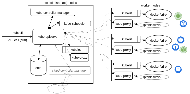
A Kubernetes cluster is made of two main parts, the cp nodes and the worker nodes. The cluster is controlled through API calls to operators, both internally and from external traffic. Most of thr processes that occur in the cluster run in containers.
Control plane node
The cp node are responsible for running the manager processes for the cluster. As Kubernetes continues to mature, more components are developed for dedicated handling of certain needs. An example of this is the cloud-controller-manager which handle interactions with tooling that sits on top of Kubernetes, but these processes were once part of the kube-controller-manager.
It is common place to have add-ons for a production cluster that handle specific tasks, like DNS services or cluster-level logging and monitoring.
Conceptually, the cp is the various pods responsible for ensuring the current cluster state matches the desired state. For clusters build with kubeadm, kubelet processes are managed by systemd and once running it will start every pod found in /etc/kubernetes/manifests/.
kube-apiserver
The kube-apiserver is responsible for all calls to the cluster (internal and external) and is central to the operation of the cluster. It accepts and validates all action of the cluster, as well as validating and configuring all data for API objects, and handles all REST operations. Thw kube-apiserver is also the only part of the cluster that has connection with the etcd database.
As of v1.18, there is a beta Konnectivity service that separates user traffic from the internal server traffic. Until this feature was added, all traffic was not segregated which had performance, capacity, and security ramifications.
kube-scheduler
The kube-scheduler is in charge of scheduling which nodes will host which Pods. The scheduler will view available resources to bind, and will try and retry to deploy the Pods depending on availability and success.
Custom schedulers can also be used to use a different algorithm than the default methodology. There also several ways to affect how pods get applied with the default algorithm, such as taints and tolerations, as well as wth metadata labels
The code for the scheduler can be found here to view the specifics of what is going on under the hood.
etcd database
Cluster state, networking, and all other persistent information is all stored in an etcd database (which is a b+tree key-value store). Values are always appended to the end and previous copies of data are marked for removal by compaction processes. It works with curl abd other HTTP libraries.
All requests to update values travel via the kube-apiserver, which then passes along the request to etcd. For simultaneous requests, the first request would update the database and the second request would not have the same version number and the kube-apiserver would respond with a 409 error to the requester. There is no further logic past the denial, so it is on the client to act upon a denial to push an update to the database.
etcd consists of a Leader database with possible followers, or non-voting Learners who are joining the cluster. They have ongoing communication to determine which will be the Leader or to determine a new one in case of a failure.
etcd is very fast and has the potential for durability, although there are some hiccups with new tools (kubeadm included) and features (like upgrading the entire cluster). While most Kubernetes objects are designed to be transient microservices, etcd is the exception and cannot be terminated without any concern like most others. Because it is the persistent state of the cluster care must be taken to protect and secure it. Before any upgrades or maintenance. etcd should be backed up. The etcdctl command allows for this with snapshot save and snapshot restore.
Other agents
The kube-controller-manager is a core control loop daemon, which along with the kube-apiserver, determines the state of the cluster. When the state does not match, the kube-controller-manager contacts the controller responsible for getting the state to where it need to be. There are several operators in use (endpoint, namespace, replication) and the list has grown as Kubernetes matures.
In beta since v1.11, the cloud-controller-manager, or ccm, interacts with agents outside the cluster. It's processes where once managed by the kube-control-manager. Splitting out these processes allows for faster changes without changing the core Kubernetes control process. Each kubelet needs to use the --cloud-provider-external settings passed to the binary. A custom ccm can also be developed and deployed as a daemonset as an in-tree or out-of-tree deployment. It is an optional component and takes some steps to enable. You can learn about them here.
Depending on the networking plugin, there could be various pods to handle network traffic. To handle all DNS queries, Kubernetes service discovery, and other function CoreDNS server has replaced kube-dns. The ability to use chained plugins allows for the server to be easily extensible.
Worker nodes
All the nodes run the kubelet and kube-proxy as well as a container engine. Other management daemons watch these agents or enhance functionality for services not yet included by Kubernetes.
The kubelet interacts with the container engine and makes sure the containers that should be running are. The kube-proxy handles all the networking to the containers using iptable entries. The kube-proxy also has a userspace mode to monitor Services and Endpoints using a random port to proxy any traffic using ipvs. Depending on the network plugin chosen, you may also see pods for the plugin.
Each node could run in a different engine and it is likely that Kubernetes will support more container runtimes as it continues to mature.
While not part of a typical installation, some users will user supervisord to monitor the kubelet and docker processes and restart them in they fail and log events. Kubernetes does not yet have cluster-wide logging, and instead the CNCF project Fluentd is used, which when implement correctly, gives a logging layer for the cluster which can filter, buffer, and route messages.
Metric on a cluster-wide scale is another lacking area of Kubernetes. There is a metrics-server SIG which gives basic functionality to collect CPU and memory utilization of a node or pod. For more complete metrics, many use the Prometheus project.
Kubelet
The kubelet systemd process accepts the API calls for Pod specification (known as a PodSpec which is a JSON or YAML file that describes a pod) and works to configure the local node to meet the specification. The kubelet is also responsible for the following:
- Mounting volumes to Pod
- Downloading secrets
- Passing requests to local container engine
- Reporting Pod and node status to cluster
The kubelet also calls other components like the Topology Manager, which uses hints to configure topology-aware resource NUMA assignments for CPU and hardware acceleration. This is off by default as it is an alpha feature.
Operators
Operators (also known as controllers or watch-loops) as important concepts for orchestration. Kubernetes has many that come with it, and it can be extended with custom operators. Operators work as two parts, an Informer and a downstream store in the form of a DeltaFIFO queue. The loop process receives an obj (object) comprised of an array of deltas from the queue. The operator's logic then creates/modifies some object until it matches the specification, as long as the delta is not a Deleted type.
The Informer calls on the API server to request the object state and the data is then cached to minimize transactions to the API. There is also a SharedInformer for objects used by multiple others which creates a shared cache fo multiple request.
There is also a Workqueue which takes keys to had out tasks to workers. They use standard Golang work queues (rate limiting, delayed, and time queue) typically.
The endpoints, namespace, and serviceaccounts operators each manges the Pod resources they are named after.
Deployments manage replicaSets. replicaSets manage Pods that share the same podSpec. Each Pod managed by a replicaSet is called a replica.
Service operators
A service is a operator which listens to the endpoint operator to provide a persistent IP for a Pod. This is needed due to the decoupling of objects and agents which allows for flexible connection of resources and reconnection on replacement.
The service operator send messages via the kube-apiserver to the kube-proxy of each node and also to the network plugin.
Services also handle access policies for inbound requests which help control resources and security.
The key takeaways on services are:
- Connects Pods
- Exposes Pods to Internet
- Decouples settings
- Defines access policies for Pods
Pods
While point of Kubernetes is to orchestrate containers, the smallest unit we deal with is a Pod. Pods can contain multiple containers and due to sharing resources, the Pod is designed to run a one-process-per-container architecture.
- Pod of whales (to stick with the Docker theme)
- Peas in a pod
The containers of the Pod start up in parallel and there is not a way to determine which becomes available first. Using InitContainers can order their startup to some extent. To support the single process running in a container, the other containers may handle logging, proxies, or special adapters.
Most network plugins give the Pod one IP to share across the containers. For the containers to talk to one another they must do so via IPC, the loopback interface, or with a shared file system.
One of the most common cases for having more than one container in a Pod is for logging. This would be an example of a sidecar container, which is dedicated to performing a helper task.
Rewrite legacy applications
It can be costly to move legacy applications to work as containerized, decoupled microservices. Can the application be containerized as is or does it need to be rewritten? Here's some of the challenges of legacy infrastructure and design practices and how cloud native design patterns help solve these problems
High replacement costs
With Kubernetes, here is a low cost to replace broken components since by its nature, it is designed to be decoupled. When comparing to legacy, this can be more of a challenge to fix a small issue with a monolithic application as the whole application will likely need to be updated to update the one problem area.
Large outage effect
In a legacy monolithic system, an issue with one area can bring down the whole application, while with Kubernetes decoupled and transient architecture, and outage with one microservice will not affect the entire app (depending on application and the function of the microservice experiencing the outage)
Lack of flexibility
If you are experiencing loads and need to scale resources this will affect the entire application for monolithically designed software. This is in contrast to Kubernetes, where if just one area needs to be scaled this can be done by just updating the replicaSet to manage more replicas.
With a monolithic application you are also limited to running one version unless you want to dedicate the resources to run an entirely new version. Using Kubernetes you could run different versions of specific components of your application which give the application much more flexibility.
Containers
While we cannot manipulate container directly with Kubernetes we do have control over their resources. In the PodSpec you can pass parameters to control the resources that container may use.
An example
resources:
  limits:
    cpu: "1"
    memory: "4Gi"
  requests:
    cpu: "0.5"
    memory: "500Mi"
Resourcing can also be controlled using a ResourceQuota object to set hard and sot limits in a namespace. The ResourceQuota object allows management of more than just CPU and memory and can apply to several object.
As a beta feature in v1.12, the scopeSelector field in the quota spec to run a pod at a specific priority if it has the appropriate priorityClassName in the PodSpec.
Init containers
An init container can be used to help order the startup of containers in a Pod. Init container must complete before any app containers can run, and will continue to restart until it completes if it fails.
They can have different settings for use of storage and security, and therefore utility commands can be used which the app would not be allowed to. They can also contain code or utilities the app does not.
TODO
What would be a good example for the use case of an init container
Here is an example of the definition of an initContainer that requires the ls command to succeed before starting a database.
spec:
  containers:
  - name: main-app
    image: databaseD
  initContainers:
  - name: wait-database
    image: busybox
    command: ['sh', '-c', 'until ls /db/dir ; do sleep 5; done; ']
Other options to determine startup order are LivenessProbes, ReadinessProbes, and StatefulSets but they add complexity.
Component review
Now that we have an understanding of the components that make up Kubernetes, lets review the architecture again.
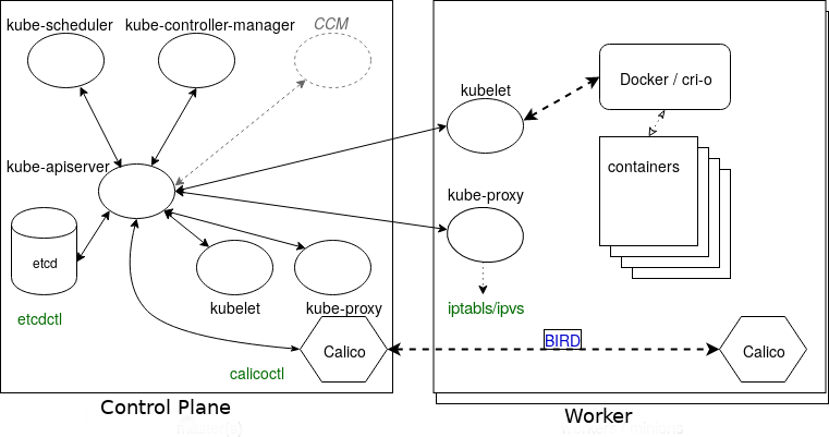
We can see that all the components talk to the kube-apiserver, and only it will talk to the etcd database.
In green, we can also see some commands that will help interact some of the other components.
Specifically there is the etcdctl command to work with etcd directly, and the calicoctl command to get networking information from Calico. The primary Calico component on each node also has a daemon, called Felix. It is responsible for monitoring and managing the network interface, route programming, ACL configuration and state reporting.
On the diagram is also BIRD, which is a dynamic IP routing daemon that is utilized by Felix. It reads the state of the routing and distributes it to the other nodes of the cluster. This allows a client to connect to any node and eventually the desired container's workload even when it is not the original node contacted.
API call flow
Imagine a scenario where you want to create a new deployment on the Kubernetes cluster. To do this maybe you run something like, 'kubectl create deploy test1 --image=httpd`. This request goes to the kube-apiserver and the API calls on etcd to persist the request.
The kube-controller-manager then requests the kube-apiserver to see if there has been any change in the spec. In this case, there has been a change because of the request coming in. The kube-apiserver then responds back to the kube-controller-manager with the new spec. Now the kube-controller-manager requests the status of this spec to see if it even exists. The kube-apiserver responds with information saying the deployment does not exist so the kube-controller-manager requests the kube-apiserver to create it. The kube-apiserver creates the spec and persists the information into etcd.
Then the same process to create the deployment is repeated to create the replicaSet. Then the process again repeats to determine the existence of a Pod.
Once the pod is created and its state is persisted into etcd, the kube-apiserver calls on the kube-scheduler to determine which node will receive this new podSpec. The kube-scheduler is always requesting information on the states of the worker nodes that is supplied by the kubelets. Once the scheduler has the information it needs, it responds with the information on which node the Pod should be sent to. The kube-apiserver then sends the information to the kubelet of that node the scheduler picked.
Networking information is sent to each of the kube-proxies by the kube-apiserver for each node so that each node (cp or worker) knows of this new networking configuration.
Finally the kubelet downloads all the config maps and secrets, and mounts any storage needed. Once the resources are available, the kubelet sends a request to the local container engine to create the Pod. The engine then returns the information to the kubelet, which in turns responds back to the kube-apiserver, which then persists the information to etcd.
Node
A node is an API object that represents a machine instance. The instance is created outside the cluster, has the necessary software installed, and then has its information ingested to the kube-apiserver to created the API object so the cluster can communicate with the new node.
Control plane nodes must be running on Linux instances, while worker nodes can also run on Windows Server 2019.
Currently, cp nodes can be created with kubeadm init and worker nodes joined with kubeadm join. The future of kubeadm promises features of being able to join secondary cp nodes or etcd nodes as well. There are other tools available to provision nodes of a cluster as well.
When the kube=apiserver cannot communicate with the kubelet of a node for over 5 minutes, the default NodeLease schedules the node to be deleted and the NodeStatus will no longer be "ready". Pods are evicted once connection to the cluster via the kube-apiserver is re-established. The cluster does not forcibly remove and reschedule them.
The node objects exist in the kube-node-lease namespace. Nodes can be removed with
kubectl delete node <node-name>
This will remove the node from the kube-apiserver and cause the pods to evacuate. Running kubeadm reset then removes the cluster specific information. Removing iptables may be necessary as well if the node is to be re-used.
Running
kubectl describe node <node-name>
will let you check the CPU usage, memory usage, requests, limits, capacity, pods allowed, current pods, among a few other things.
Single IP per pod
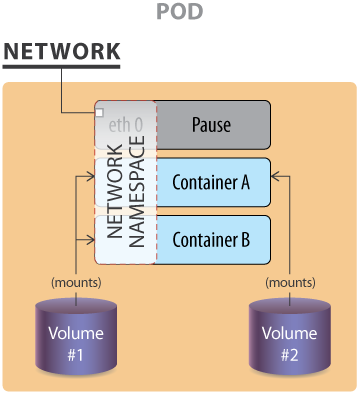
The image shows an example of a pod with two volumes, 1 and 2, and three containers, A, B, and the pause container. This pause container is used to get the an IP address and to share this network namespace with the other containers within the pod.
For the pods to communicate with one another they can use
- the loopback interface
- file writes to a common file system
- interprocess communication (IPC)
There is also a network plugin from HPE Labs that allows for multiple IPs per pod but this has not been adopted elsewhere.
Starting as an alpha feature from v1.16 you can use IPv4 or IPv6 for pods and services. Current versions require creating the network for each address family separately when creating a service.
Container to outside path
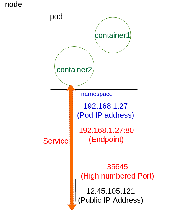
In this example the two container share an IP address and a namespace. These are configured by kubectl working with the kube-proxy. The IP is assigned to the pod before the containers are started and inserted into them on start up. The container has an interface like eth0@tun10, and the IP is set for the pod's life.
The endpoint is created at the same time as the service. Notice that the endpoint is the pod IP with a port number. The service connects the network traffic from a high number port to the endpoint using iptables along with ipvs.
The kube-controller-manager's watch loops monitors the need for creating or deleting any services and endpoints.
Services
Services are used to connect Pods to one another or to external traffic.
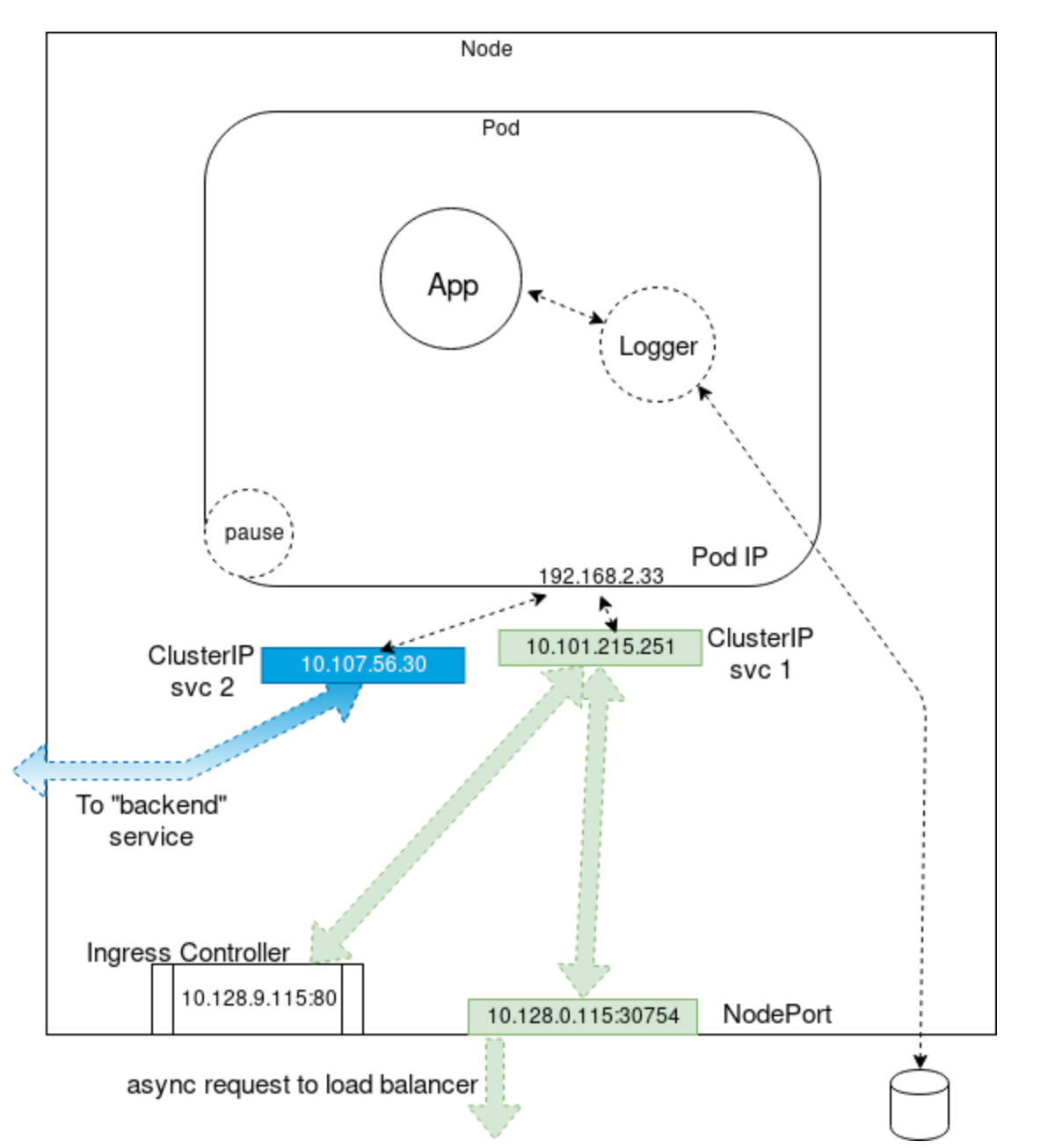
In the example, there is a primary and sidecar container, App and Logger respectively. There is also the pause container that reserves the IP address in the namespace. This container isn't seen within Kubernetes, but you could view it using docker or crictl. We also see some ClusterIPs, used to connect to either a NodePort for outside the cluster, an IngressController or proxy, or to connect to another "backend" pod.
Networking setup
From a networking perspective, each pod can be treated as a virtual machine of physical hosts. The network must assign an IP to each Pod and provide routes between all Pods on any nodes.
There are three main networking challenges in a container orchestration system:
- Coupled container-to-container communications (solved with Pod concept)
- Pod-to-pod communication
- External-to-pod communication (solved by services concept)
Kubernetes, then expects the networking configuration to handle the pod-to-pod is available, it will no do it for you.
Detailed explanation of the Kubernetes networking model can be found here in the official docs.
One of the lead developers of Kubernetes has also created this useful description of Kubernetes networking.
CNI network configuration file
To provide networking, Kubernetes has begun standardizing on the Container Networking Interface (CNI) spec. Since v1.6.0, kubeadm's goal was to use CNI.
CNI is an emerging spec with libraries that allow plug-ins to be written to container networking and remove allocated resources when containers are deleted. CNI is language agnostic and provides a common interface for various networking solutions and container runtimes. There are many plugins such as ones from Amazon ECS, SR-IOV, Cloud Foundry, and many more. With CNI you can write network configuration files:
{
  "cniVersion": "0.2.0",
  "name": "mynet",
  "type": "bridge",
  "bridge": "cni0",
  "isGateway": true,
  "ipMasq": true,
  "ipam": {
    "type": "host-local",
    "subnet": "10.22.0.0/16",
    "routes": [
      { "dst": "0.0.0.0/0" }
    ]
  }
}
The example configuration file creates a standard Linux bridge named cni0 which will give out IP address in the subnet 10.22.0.0/16. This bridge plug-in will configure network interfaces in the correct namespaces so that the container network is defined properly.
More info can be found in the CNI Github repo README.
Pod-to-pod communication
The CNI can be used to configure the network of a pod and provide a single IP address. It does not address the issue of pod-to-pod communication though.
Kubernetes requires the following:
- All pods can communicate with one another across all nodes
- All nodes can communicate with all pods
- No network address translation (NAT)
Basically all IP (nodes and Pods) are routable without NAT. This is achievable at the physical network infrastructure level when you have access to is (e.g with GKE), or via a software defined overlay like many of the networking interfaces previously discussed (Weave, Flannel, Calico, Romana, etc).
These Kubernetes docs or this list provide a more complete list.
Mesos
At a high level, there is not much difference between Kubernetes and other clustered orchestration systems.
Most have some sort of central manager that exposes an API, something to schedule and place workloads on cluster nodes, and some persistent layer for the cluster state.
For example, here is a comparison of Kubernetes and Mesos.
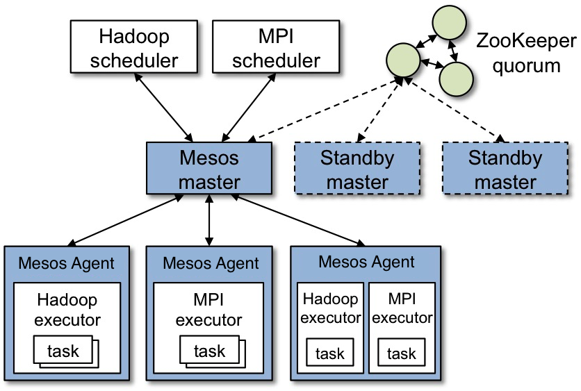
Overall the architecture is similar, just different technologies might be used for different components. In Mesos, the persistence layer is implemented with Zookeeper, while Kubernetes uses etcd.
Similar comparisons could be made for systems like OpenStack or CloudStack.
Kubernetes sets itself apart with features targeting fault-tolerance, self-discovery, and scaling. It is also differentiated with it purely API-driven mindset.
Lab Exercises
Lab 4.1 - Basic node maintenance
This lab focuses on backing up etcd and updating the Kubernetes version on the cp and worker nodes.
Back up etcd
The upgrade process for Kubernetes has become more stable but it is still good practice to backup the cluster state before trying to back it up. There are many tools for managing and backing up etcd, and each has a distinct process for backing up and restoring. We'll use the included snapshot command for etcdctl. All the following commands in this section should be run on the cp node.
- Find the data directory for the etcd daemon, which can be found in the manifest.
sudo grep data-dir /etc/kubernetes/manifests/etcd.yaml
The response should be something like this:
- --data-dir=/var/lib/etcd
- Log into the etcd container
kubectl -n kube-system exec -it etcd-<Tab> -- sh
This will open up a shell on the container. Now have a look at the commands etcdctl offers with
etcdctl -h
For TLS to work some files need to be passed to etcdctl. The etcd image is fairly minimal so many useful commands are not available. To find the necessary files, it is important to remember the path /etc/kubernetes/pki/etcd. cd to this location and list the files with echo since ls will not be available.
cd /etc/kubernetes/pki/etcd
echo *
You should get a response similar to this from echo *
ca.crt ca.key healthcheck-client.crt healthcheck-client.key peer.crt peer.key server.crt server.key
You can avoid having to type out each of these keys, especially in a limited shell environment using environment parameters. Log out with exit and pass the paths as necessary. An example is in the next step.
- Check database health with the loopback IP on port
2379. This will need the peer cert and key and the certificate authority as environment variables.
kubectl -n kube-system exec -it etcd-<Tab> -- sh \
  -c "ETCDCTL_API=3 \
  ETCDCTL_CACERT=/etc/kubernetes/pki/etcd/ca.crt \
  ETCDCTL_CERT=/etc/kubernetes/pki/etcd/server.crt \
  ETCDCTL_KEY=/etc/kubernetes/pki/etcd/server.key \
  etcdctl endpoint health"
You should get a response like this
127.0.0.1:2379 is healthy: successfully committed proposal: took = 14.813924ms
Before continuing to the next step, let's break down the command we just used. First is the kubectl -n kube-system exec -it etcd-<Tab> -- sh part, which like the step before is used to open a shell in the container. On the next line is the -c flag which is used with sh to tell it to execute the following command. The command comes next, which is wrapped in the double quotes. First, we specify our environment variables:
ETCDCTL_APIto specify the API version to useETCDCTL_CACERTto specify the path to the certificate authorityETCDCTL_CERTto specify the path to the peer certETCDCTL_KEYto specify the path to the peer key
The last part is the actual command to check the health, which is etcdctl endpoint health.
- Determine the number of databases hat are part of the cluster. 3 and 5 are common in production clusters to meet 50%+1 for quorum. For the learning environment, there will be only one.
kubectl -n kube-system exec -it etcd-ip-<Tab> -- sh \
  -c "ETCDCTL_API=3 ETCDCTL_CACERT=/etc/kubernetes/pki/etcd/ca.crt \
  ETCDCTL_CERT=/etc/kubernetes/pki/etcd/server.crt \
  ETCDCTL_KEY=/etc/kubernetes/pki/etcd/server.key \
  etcdctl --endpoints=https://127.0.0.1:2379 member list"
You should get a response like this:
d4e6be3f3fdd0375, started, <hostname>, https://<host IP>:2380, https://<host IP>:2379, false
By appending -w table to the previous command you can also view this information in a table.
+------------------+---------+-----------------+---------------------------+---------------------------+------------+
|        ID        | STATUS  |      NAME       |        PEER ADDRS         |       CLIENT ADDRS        | IS LEARNER |
+------------------+---------+-----------------+---------------------------+---------------------------+------------+
| d4e6be3f3fdd0375 | started |   <hostname>    |  https://<host IP>:2380   |  https://<host IP>:2379   |      false |
+------------------+---------+-----------------+---------------------------+---------------------------+------------+
- After figuring out the number of databases and the health we can back up etcd. We'll use the
snapshotargument to save the file to/var/lib/etcd.
kubectl -n kube-system exec -it etcd-<Tab> -- sh \
  -c "ETCDCTL_API=3 \
  ETCDCTL_CACERT=/etc/kubernetes/pki/etcd/ca.crt \
  ETCDCTL_CERT=/etc/kubernetes/pki/etcd/server.crt \
  ETCDCTL_KEY=/etc/kubernetes/pki/etcd/server.key  \
  etcdctl --endpoints=https://127.0.0.1:2379 \
  snapshot save /var/lib/etcd/snapshot.db "
And you'll get a response similar to
{"level":"info","ts":1648840656.8329804,"caller":"snapshot/v3_snapshot.go:119","msg":"created temporary db file","path":"/var/lib/etcd/snapshot.db.part"}
{"level":"info","ts":"2022-04-01T19:17:36.839Z","caller":"clientv3/maintenance.go:200","msg":"opened snapshot stream; downloading"}
{"level":"info","ts":1648840656.841397,"caller":"snapshot/v3_snapshot.go:127","msg":"fetching snapshot","endpoint":"https://127.0.0.1:2379"}
{"level":"info","ts":"2022-04-01T19:17:36.890Z","caller":"clientv3/maintenance.go:208","msg":"completed snapshot read; closing"}
{"level":"info","ts":1648840656.900381,"caller":"snapshot/v3_snapshot.go:142","msg":"fetched snapshot","endpoint":"https://127.0.0.1:2379","size":"4.0 MB","took":0.067326355}
{"level":"info","ts":1648840656.9014206,"caller":"snapshot/v3_snapshot.go:152","msg":"saved","path":"/var/lib/etcd/snapshot.db"}
Snapshot saved at /var/lib/etcd/snapshot.db
After creating the snapshot, verify it is there with
sudo ls -l /var/lib/etcd/
And the response should look like
total 3916
drwx------ 4 root root    4096 Apr  1 17:47 member
-rw------- 1 root root 4001824 Apr  1 19:17 snapshot.db
- Now backup the snapshot and the other information used to create it.
mkdir $HOME/backup
sudo cp /var/lib/etcd/snapshot.db $HOME/backup/snapshot.db-$(date +%m-%d-%y)
sudo cp /root/kubeadm-config.yaml $HOME/backup/
sudo cp -r /etc/kubernetes/pki/etcd $HOME/backup/
It is good practice to crete snapshots on a regular basis, using a cronjob or some other scheduling tool to create them.
When using the snapshot restore functionality, the database cannot be in use. In an HA cluster, the control plane would be removed and replaced and a restore would not be needed. Official documentation on restoring etcd can be found in the Kubernetes docs here
Upgrading the cluster
note
'kubeadm' only supports updating versions 1.n.x to 1.n+1.x and 1.n.x to 1.n.y, where (y > x).
For example, if the cluster is built with kubeadm 1.22.1, to upgrade to the next major version you would need to go to 1.23.1, and not 1.23.4. You could however go from 1.22.1 to 1.22.4
- Upgrade the package metadata and list the available versions of kubeadm that can be installed.
sudo apt update
sudo apt-cache madison kubeadm
You should get something like
 kubeadm |  1.22.3-00 | http://apt.kubernetes.io kubernetes-xenial/main amd64 Packages
 kubeadm |  1.22.2-00 | http://apt.kubernetes.io kubernetes-xenial/main amd64 Packages
 kubeadm |  1.22.1-00 | http://apt.kubernetes.io kubernetes-xenial/main amd64 Packages
 kubeadm |  1.22.0-00 | http://apt.kubernetes.io kubernetes-xenial/main amd64 Packages
 kubeadm | 1.21.11-00 | http://apt.kubernetes.io kubernetes-xenial/main amd64 Packages
 kubeadm | 1.21.10-00 | http://apt.kubernetes.io kubernetes-xenial/main amd64 Packages
 kubeadm |  1.21.9-00 | http://apt.kubernetes.io kubernetes-xenial/main amd64 Packages
 kubeadm |  1.21.8-00 | http://apt.kubernetes.io kubernetes-xenial/main amd64 Packages
 kubeadm |  1.21.7-00 | http://apt.kubernetes.io kubernetes-xenial/main amd64 Packages
 kubeadm |  1.21.6-00 | http://apt.kubernetes.io kubernetes-xenial/main amd64 Packages
 kubeadm |  1.21.5-00 | http://apt.kubernetes.io kubernetes-xenial/main amd64 Packages
 kubeadm |  1.21.4-00 | http://apt.kubernetes.io kubernetes-xenial/main amd64 Packages
 kubeadm |  1.21.3-00 | http://apt.kubernetes.io kubernetes-xenial/main amd64 Packages
 kubeadm |  1.21.2-00 | http://apt.kubernetes.io kubernetes-xenial/main amd64 Packages
 kubeadm |  1.21.1-00 | http://apt.kubernetes.io kubernetes-xenial/main amd64 Packages
 kubeadm |  1.21.0-00 | http://apt.kubernetes.io kubernetes-xenial/main amd64 Packages
- Remove the hold on
kubeadm, install the next version ofkubeadm, and then add the hold back to the package to prevent unintended updates.
sudo apt-mark unhold kubeadm
sudo apt-get install -y kubeadm=1.22.1-00
sudo apt-mark hold kubeadm
note
In chapter 3 we installed kubeadm=1.21.1-00 so we must go to kubeadm=1.22.1-00
Then check the version to confirm the update was successful.
kubeadm version
kubeadm version: &version.Info{Major:"1", Minor:"22", GitVersion:"v1.22.1", GitCommit:"632ed300f2c34f6d6d15ca4cef3d3c7073412212", GitTreeState:"clean", BuildDate:"2021-08-19T15:44:22Z", GoVersion:"go1.16.7", Compiler:"gc", Platform:"linux/amd64"}
- Prepare the cp node for updates. To do this we first need to evict as many pods as possible. By nature, daemonsets are on every node, and some, like the Calico ones, must remain.
kubectl drain <node name> --ignore-daemonsets
- Once drained, you can upgrade the node. First you will want to see the upgrade plan. You will see different versions you can upgrade to but remember you will want to go from 1.n.x to 1.n+1.x, so for example, from 1.21.1 to 1.22.1. The upgrade plan will give you a detailed outline of the changes the upgrade will make.
sudo kubeadm upgrade plan
Once you have reviewed the plan you can apply the upgrade. The command will give you a preview and ask you to confirm you want to upgrade. Review the preview and confirm to upgrade the node to the new version.
sudo kubeadm upgrade apply v1.22.1
Check your CNI to get a compatible version with the new cluster version
Now check the node status. It should be
SchedulingDisabled. Run
kubectl get nodes
and you should get a response like
NAME              STATUS                     ROLES                  AGE   VERSION
cp-node           Ready,SchedulingDisabled   control-plane,master   42d   v1.21.1
worker-node       Ready                      <none>                 40d   v1.21.1
We also need to update the other software and restart the daemons. First release the holds we set in the last lab, then upgrade both packages and add the hold back.
sudo apt-mark unhold kubelet kubectl
sudo apt-get install -y kubelet=1.22.1-00 kubectl=1.22.1-00
sudo apt-mark hold kubelet kubectl
Finally, restart the daemons.
sudo systemctl daemon-reload
sudo systemctl restart kubelet
Now get the nodes again to verify the cp has been upgraded with
kubectl get nodes
and you should see something like
NAME              STATUS                     ROLES                  AGE   VERSION
cp-node           Ready,SchedulingDisabled   control-plane,master   42d   v1.22.1
worker-node       Ready                      <none>                 40d   v1.21.1
- Now we can make the cp node available to the scheduler again.
kubectl uncordon <node name>
and verify the ready status with
kubectl get nodes
and you should no longer see the SchedulingDisabled as the STATUS.
NAME              STATUS                     ROLES                  AGE   VERSION
cp-node           Ready                      control-plane,master   42d   v1.22.1
worker-node       Ready                      <none>                 40d   v1.21.1
- Now we must update the worker node.
important
Most of the next commands will need to be run on the worker node. There are a few commands that need to be run on the cp node. Commands that need to be run on the cp node will be in these blocks.
First, unhold, upgrade, and rehold kubeadm.
sudo apt-mark unhold kubeadm
sudo apt-get update
sudo apt-get install -y kubeadm=1.22.1-00
sudo apt-mark hold kubeadm
- Next, on the cp node, drain the worker node.
important
kubectl drain <worker node name> --ignore-daemonsets
- Now, on the worker upgrade the node.
sudo kubeadm upgrade node
- Now unhold, upgrade, and rehold the other software.
sudo apt-mark unhold kubelet kubectl
sudo apt-get install -y kubelet=1.22.1-00 kubectl=1.22.1-00
sudo apt-mark hold kubelet kubectl
- Restart the deamons for the upgrade to take effect.
sudo systemctl daemon-reload
sudo systemctl restart kubelet
- Now, back on the cp, check the node status.
important
kubectl get nodes
You should see the worker needs to be uncordoned now to allow the scheduler to use it.
NAME              STATUS                     ROLES                  AGE   VERSION
cp-node           Ready                      control-plane,master   42d   v1.22.1
worker-node       Ready,SchedulingDisabled   <none>                 40d   v1.22.1
Uncordon the worker node and check the status to make sure both nodes are Ready.
important
kubectl uncordon <worker node name>
kubectl get node
Once both nodes are ready the statuses should look like
NAME          STATUS   ROLES                  AGE   VERSION
cp-node       Ready    control-plane,master   42d   v1.22.1
worker-node   Ready    <none>                 40d   v1.22.1
note
This process was run through again to get to v1.23.1 to match the course notes, swapping anywhere it says 1.22.1 for 1.23.1.
Lab 4.2 - Working with CPU and memory constraints
This section of the lab focuses on resource limits, namespaces, and more complex deployments. We will again use the cluster we have been building up over the past lab exercises. SSH into the cp node and run all the commands for this section there.
- First, we will deploy a container called
stressto generate load on the cluster, and then verify it is running.
kubectl create deployment hog --image=vish/stress
kubectl get deployments
Once the deployment is ready you should see
NAME   READY   UP-TO-DATE   AVAILABLE   AGE
hog    1/1     1            1           11s
- Next, describe the deployment and then view the output as a YAML. Notice there is not settings limiting the resource use currently, just
{}.
kubectl describe deployment hog
kubectl get deployment hog -o yaml
The resources field in the YAML can be found under spec.template.spec.containers and is a setting in each container listed.
- Write the deployment YAML to a file so we can add some resource limits.
kubectl get deployment hog -o yaml > hog.yaml
vim hog.yaml
Once the file is open in vim, add the following four lines (make sure to indent properly) under the resources section:
limits:
  memory: "4Gi"
requests:
  memory: "2500Mi"
- Replace the deployment and verify the change. You should see the new resources set in YAML output this time matching what you added to the YAML file.
kubectl replace -f hog.yaml
kubectl get deployment hog -o yaml
- now go look at the
stdioof the hog container. Get the pod name, and then look at the container logs.
kubectl get pods
kubectl logs <hog pod name>
The logs should look something like
I0405 16:49:23.354678       1 main.go:26] Allocating "0" memory, in "4Ki" chunks, with a 1ms sleep between allocations
I0405 16:49:23.354726       1 main.go:29] Allocated "0" memory
Open a second and third terminal and ssh into the cp node and worker node. Run top in each to view the memory usage. You should not be seeing stress as it should not be using enough resources to be seen in the list.
- Now let's edit the hog.yaml file again to consume some CPU and memory. Open the file with
vimand add the following:
Change the resources section to
limits:
  cpu: "1"
  memory: "4Gi"
requests:
  cpu: "0.5"
  memory: "2500Mi"
and below the resources add a new argument called args with the following:
args:
- -cpus
- "2"
- -mem-total
- "950Mi"
- -mem-alloc-size
- "100Mi"
- mem-alloc-sleep
- "1s"
- Now delete the deployment and recreate it.
kubectl delete deployment hog
kubectl create -f hog.yaml
You should now see high usage from stress in the top table.
note
If the top table does not show high usage the workload or the container may have failed.
To check you can get the pods and check the logs
kubectl get pods
kubectl logs <pod name>
The logs and whether the pod is running should give you an idea of what kind of error you have
- Not running is likely a missing parameter
- Running is likely an improperly set parameter
Lab 4.3 - Resource limits for a namespace
Limits can be set on the deployment level, or at the namespace level. In this lab section we will create a namespace with resource limits and then create another hod deployment to run within that namespace, and it should be limited to less resource than the previous hog deployment.
- First, we'll create the new namespace, 'low-usage-limit`.
kubectl create namespace low-usage-limit
kubectl get namespace
Then create a YAML to define the resource limits for the namespace. It should be of kind LimitRange.
vim low-resource-range.yaml
and it should contain
apiVersion: v1
kind: LimitRange
metadata:
  name: low-resource-range
spec:
  limits:
  - default:
      cpu: 1
      memory: 500Mi
    defaultRequest:
      cpu: 0.5
      memory: 100Mi
    type: Container
- Now we can create the
LimitRangeobject in the new namespace.
kubectl -n low-usage-limit create -f low-resource-range.yaml
And verify it worked
kubectl get LimitRange --all-namespaces
Don't forget the --all-namespaces flag, otherwise it will just show the LimitRanges in the default namespace and you will not find anything.
- Now create a new deployment in the new namespace.
kubectl -n low-usage-limit create deployment limited-hog --image=vish/stress
kubectl get pods --all-namespaces
notice, the first hog deployment is still running.
You can view just the pods in the namespace with
kubectl -n low-usage-limit get pods
Look at the pod details as well.
kubectl -n low-usage-limit get pod <limited-hog pod name> -o yaml
Notice the resources are inherited from the LimitRange.
- Now copy the original
hog.yamldeployment file and update thenamespacefield with the new one we created and also delete theselflinkif it exists.
cp hog.yaml hog2.yaml
vim hog2.yaml
And then create a new deployment with the new YAML that was just modified.
kubectl create -f hog2.yaml
kubectl get deployments --all-namespaces
You should see a new deployment named hog in the limited-usaged-limit namespace.
In another window use
topto view the usage on the nodes. You should see the newhogdeployment and the original one at the op of the list using the same amount of resources. This is because the deployment level limits override any in the namespace.Delete the deployments to recover system resources.
kubectl -n low-usage-limit delete deployment hog
kubectl delete deployment hog
Knowledge check
- The smallest object or unit that can be worked with in Kubernetes is the Pod
- One IP address can be configured per Pod
- The main configuration agent on a master server is the kube-apiserver
- The main agent on a worker node is a kubelet
- A Service connects other resources together and handles Ingres and Egress traffic